Filter Properties and their Pole-Zero Plots
The transfer function  represents a characteristic of a linear, time-invariant system (or filter). We can determine a lot about the system simply based on the location of the poles and zeros. Below we discuss some of these properties.
Causal
A filter is causal if all of the poles correspond to causal systems and that the number of poles  the number of zeros. Below is an example (pole-zero plot and impulse response) of a causal filter.
Causal Filter


Acausal Filter


Stability
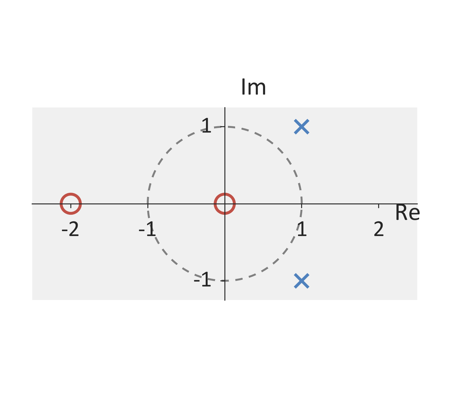
If the filter is causal, the filter is stable if all of the poles are inside the unit circle. More generally (for any filter that is casual / anti-causal / acausal), the filter is stable if the region of convergence includes the unit circle. Below is an example (pole-zero plot and impulse response) of an unstable and a stable filter.
Stable Filter


Unstable Filter


Finite Impulse Response (FIR)
The filter is FIR if the poles are only found at  or
 . Below is an example (pole-zero plot and impulse response) of an FIR filter.
FIR Filter


Infinite Impulse Response (IIR)
The filter is IIR if the poles are found locations other than or . Below is an example (pole-zero plot and impulse response) of an IIR filter.
IIR Filter


Linear Phase (Symmetric Impulse Response)
The filter has a linear phase if the poles and zeros are symmetric around the unit circle. Note that symmetric in this case means that if  is the location of a pole or zero, then
 must also be the location a pole or zero (both must be poles or both must be zeros). Due to the requirement that poles need to be symmetric around the unit circle, the causal, IIR filter cannot be simultaneously both stable and linear phase.
A filter is still considered linear phase if there are discontinuities that jump by increments of  . These jumps correspond to negative values in the frequency response.
Below is an example (pole-zero plot and impulse response) of a linear phase filter with symmetric poles and zeros.
Linear Phase Filter (Symmetric Zeros, Even Impulse Response)


Linear Phase Filter (Symmetric Poles)


Linear Phase Filter (Symmetric Zeros, Odd Impulse Response)


Invertible
The filter is invertible if the inverse filter is stable. The inverse reverses the poles and zeros. Below is an example (pole-zero plot and impulse response) of an invertible filter and non-invertible filter.
Invertible Filter


Non-Invertible Filter


Minimum Phase
The filter is a minimum phase system if the system and its inverse are both causal and stable. This is equivalent to (1) all of the poles and zeros are inside the unit circle and (2) the number of poles equal the number of zeros (not counting poles or zeros at infinity).
Below is an example (pole-zero plot and impulse response) of a minimum phase filter.
Minimum Phase Filter


